Battery BMS development
2017-05-16
kWeld power supply recommendations
2017-08-29A batch of three charger prototypes from the first of two suppliers have arrived, and I took the time to test them for performance, reliability and safety. They do have some remaining issues, but I am happy that the first prototypes are close to acceptable. The biggest issue is that the certifications documents that I had received beforehand are related to a very similar model, but apparently not for the ordered one. That is what you have to expect when dealing with Asian manufacturers. I cross fingers that this was just a mistake. The documents were good and the approval is from a certified institute, but that doesn’t really help…
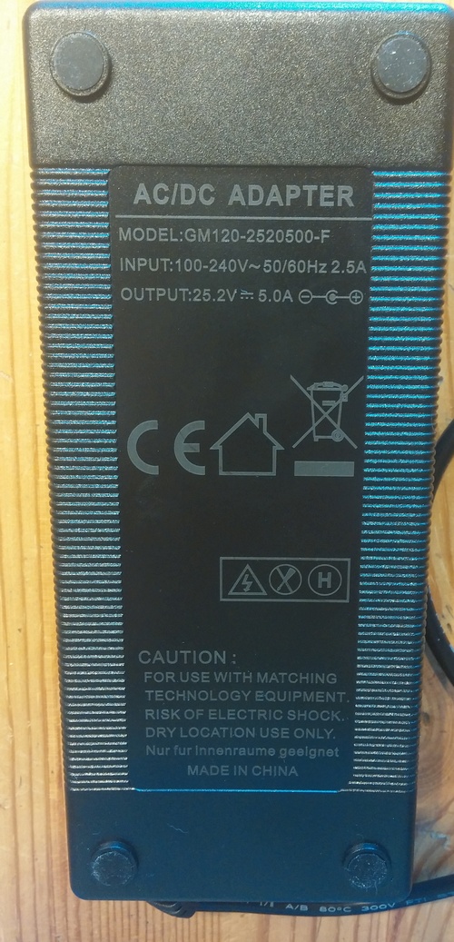
The most important target specs are:
– 25.2V +-1%
– 5.0A +-5%
– short-circuit protection
– universal AC input with C13 socket
– continuous operation at 10 ~ 35°C
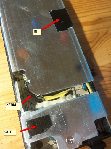
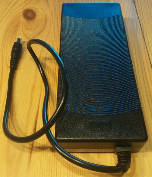
Here are some teardown pictures of the unit.
Top view:
Bottom view:
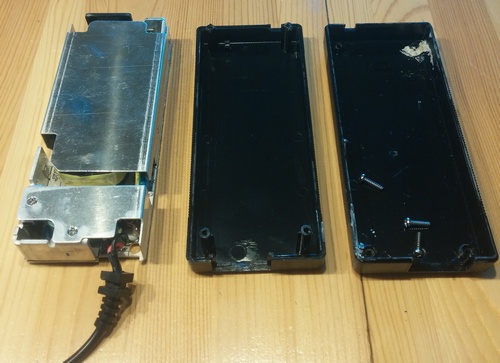
Casing removed:
Heat sinks removed:
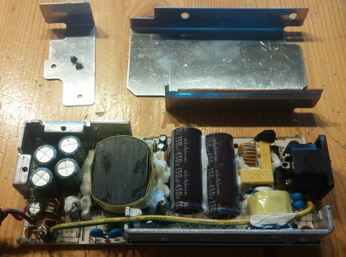
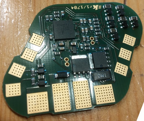
PCB view from top:
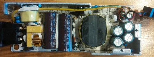
PCB view from bottom:
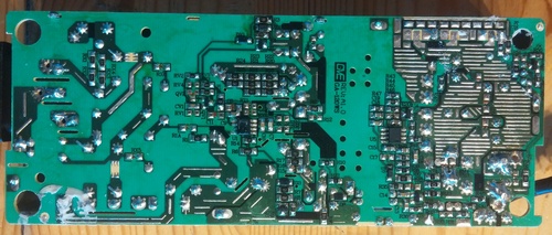
The unit is well designed in terms of clearance / creepage.
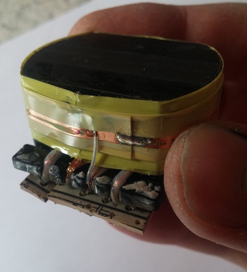
As the main transformer is a crucial part to ensure safety, I sacrificed one unit and took that component apart.
Outer insulation sheet removed, revealing EMI shielding:
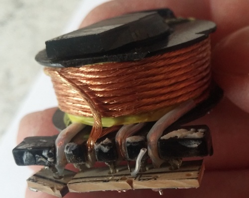
Outer section of primary winding:
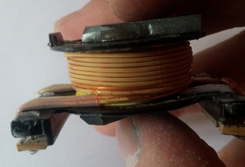
Secondary winding:
Inner section of primary winding, plus auxiliary:
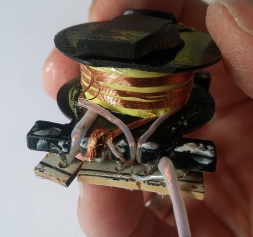
Although I had to criticize that not all primary winding ends had received silicone tubing, the unit can be considered well constructed, because a) its low voltage side is earthed, and b) the secondary is triple-insulated. In fact, the insulation is thicker than the copper core.
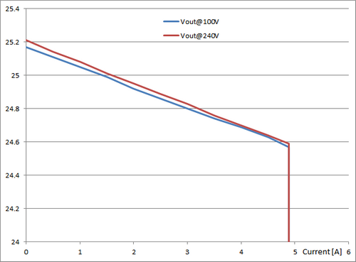
The performance measurement results show that the unit is working as expected.
Output voltage versus output current at minimum and maximum AC input voltage:
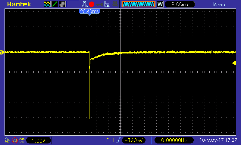
Transient response, no load to full load @240V (the large glitch is caused by the electronic load, it produces a 100µs short before stabilizing the load current):
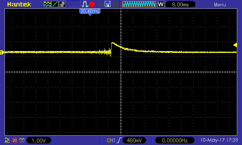
Transient response, full load to no load @240V:
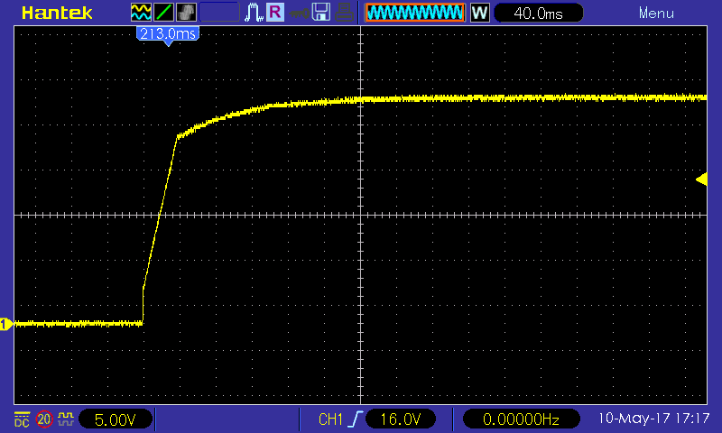
Power up with no load @240V:
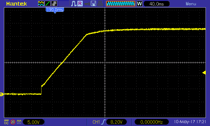
Power up with 3.7A load @240V:
Also the temperatures are reasonable and promise an acceptable lifetime:
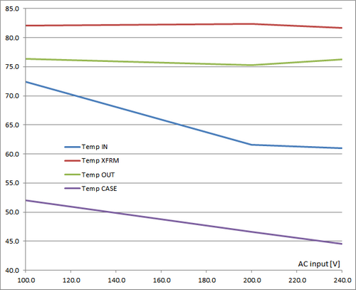
This picture shows the measurement points. “Temp CASE” represents the hottest spot measured at the case. All temperatures were taken with an IR thermometer. To obtain realistic results, the unit was operated for 60 minutes with the casing assembled. After that time, I quickly removed the top cover and measured the temperatures at all internal locations within 10 seconds.