We’re online!
2017-03-15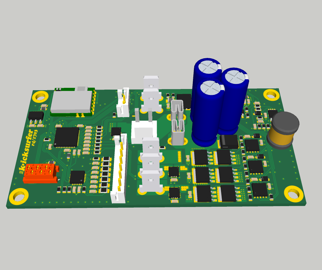
board rev.4 is finished & ordered
2017-03-25
The keenlab kit uses a brushless motor in combination with a custom controller running Field Oriented Control software. The motor has no sensors, so the controller has to operate in sensorless mode, requiring it to estimate the instantaneous (electrical) rotor phase from just observing the motor phase voltages and currents. If that estimation would not be working properly, the motor would run inefficiently without us being able to recognize that easily. As there is no direct way to measure phase voltages and current in relation to the motor’s mechanical orientation, we came up with an indirect method.
The following tools are needed:
- a 2 channel oscilloscope
- a small but strong permanent magnet
- a digital Hall sensor, for example TLE4905L
- a current probe (alternatively: shunt resistor), for example Hantek CC-65
STEP 1: determine electrical motor phase voltage in relation to mechanical orientation
00:00. the three phases are joined into a virtual star ground via three identical resistors. Oscilloscope channel 2 is connected to the “yellow” phase, ground is connected to virtual star node.
00:17. the digital Hall sensor is connected to oscilloscope channel 1. Supply voltage is 20V (main servo controller bus voltage), the output has a 1k pullup. A magnet (from old hard disk) is taped to motor under test.
00:00. the motor is turned by hand, the scope triggers on falling edges of the Hall sensor. The sensor/magnet arrangement is carefully adjusted such that the zero crossing of the back-emf voltage coming from phase “yellow” conincides with the trigger. (Is is a zero crossing going from positive to negative here because that was easier to achieve mechanically – the initial magnet / Hall sensor arrangement was closer to this one. Which one to choose is not important.)
00:08. zooming in vertically and horizontally to check that zero crossing is right on spot.
STEP 2: verify phase current during FOC operation
00:00. FOC controller is configured for velocity control, motor is running. Pay attention to configure the controller such that the rotation direction is identical to step 1 – otherwise the oscilloscope would trigger on the wrong edge. The current probe is connected to channel 2, and set up to measure the current flowing through the “yellow” phase. The Hall sensor setup remains untouched and stays connected to oscilloscope channel 1.
00:00. channel 2 is showing the current though the motor phase. 1V equals 1A. The motor is not loaded at this moment, only little current flows.
00:03. the motor is loaded, which is easy in our case: touch the rubber wheel with a finger and use that as a brake. It can clearly be recognized that the zero crossing of the current waveform is again right at the negative edge of the Hall sensor signal.
At this point, we know for phase “yellow”, that the current waveform that the FOC algorithm generates on this motor phase under load, has the same phase as the back-emf voltage from that very same phase. BLDC theory tells us (although we won’t go into that here) that this is the condition that gives us the perfect phase between the rotor’s permanent magnets and the stator’s magnet field orientation: 90 degrees. This guarantees that the motor generates the most torque from the current flowing through it, maximizing efficiency.
To validate expected performance of the sensorless rotor orientation estimator as part of the FOC package, this procedure needs to be repeated under various velocities and shaft load situations.
2 Comments
Are you testing the controller for accuracy in synchronizing with the wheel movement or do you plan to add the hall effect sensor as in put to the controller?
What you wrote first – I am testing the angular accuracy of the sensorless rotor angle estimator. That is not automatically given, and if the software performs bad on this it will directly and massively influence the system efficiency.