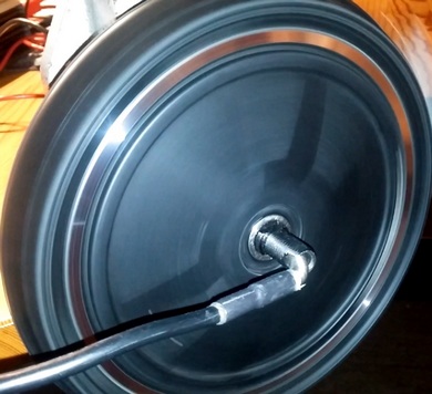
BLDC motor and FOC controller phase current validation
2017-03-15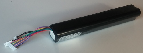
Pre-series batteries arrived!
2017-05-16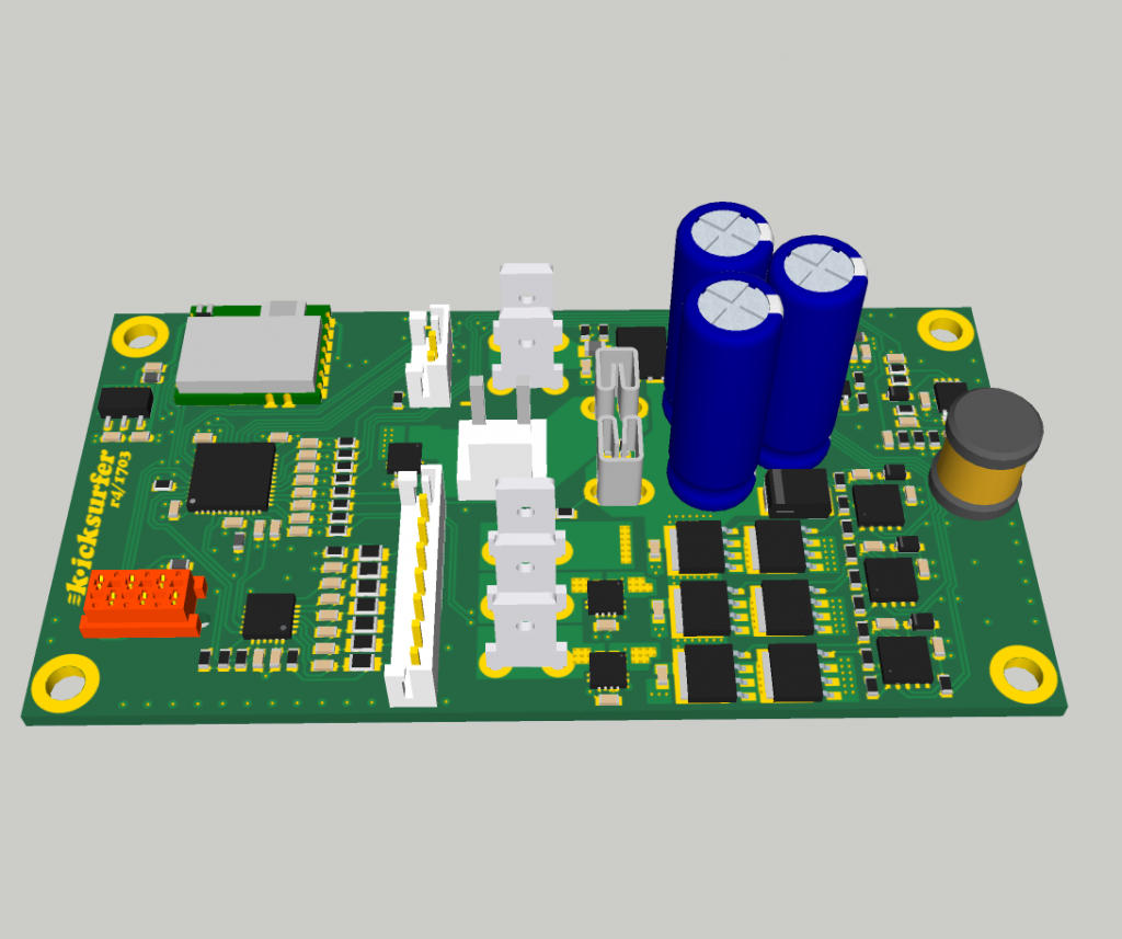
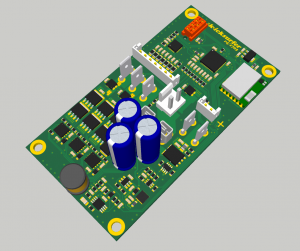
here is a first 3D impression of the new design:

Two boards have just been ordered from PCB-Pool and should arrive in 8 work days.
Here is a summary of all features of this board:
- STM32F103CBU6 microcontroller (128k flash, 20k RAM, 72MHz ARM Cortex M3)
- 3-phase brushless motor driver with phase current measurement for FOC operation
- 30V / 15A continuous, 25A short time
- charging port with integrated BMS for 6-cell LiPo or LiIon pack
- Bluetooth 3.0 radio for telemetry, configuration and firmware update
- inductive proximity sensor
- low-power standby (50uA) and wakeup from motor or charging port
- board size 84 x 44 mm, 4 layer construction
The major changes from rev.3 are
- strengthened the motor phase PCB traces, now using three layers instead of two
- added Bluetooth radio
- improved startup behavior of inductive proximity sensor
- removed buzzer, the firmware can now use the motor for audible feedback
- minor bug fixes
6 Comments
Great stuff here and very nice job.
What do you mean by “Field Oriented Control”?
Also what does the proximity sensor do?
Is there active phase feedback (e.g. hall sensor) from the motor to the driver?
I am not sure if it is a good idea to put the BMS on this board. BMS can be easily bought off the shelf, and depending on how many cells in series, you may have to use a different BMS. A balancer/protection board is about $8 and a charger board is about $10. Power supply another $20. I am not sure why you need to design your own BMS.
Just google “Field Oriented Control” or “FOC” or “Vector control”, it is not easy to explain in a few words. That is more and more also used in the RC area, as it gives you real motor torque control. Standard controllers only translate the throttle signal into voltage. Current develops depending on motor velocity and resistance, which is why my 1:8 monster truck just flips over when you throttle too hard.
The proximity sensor is to driver detection, it is not related to the motor. The motor controller is sensorless, it calculates the rotor angle from its voltage and current feedback.
I designed the BMS mainly because according to UN38.3 it is forbidden to ship unprotected lithium batteries in regular mail. For those, you need to add warning signs, special documents, and you are restricted to sending samples in limited quantity only. You will now say that they are all doing it, but you should ask yourself where all these batteries come from – China. They don’t care. I do.
And my BMS has some nice features that you won’t find everywhere. It can be connected to a controller or a PC, and you can read out the battery state, or you can change its parameters. A balancer is also included, and look how small the thing is – for 6 cells. And it perfectly fits into the battery construction. And once you know the price at which I will be able to sell it, you will know. I beat all your figures above 🙂
Thank you for your explanations. Please note that a 6s configuration of 6 cells is not very interesting. You need to go to at least 36 volts (10s) or better yet 48 volts (13s). This is a serious device and needs to have lots of power and energy storage. You will need at least 0.5 kWh. If you plan to do a redesign, I would advise to go to at least 10s.
The motor is a 3 phase AC brushless motor. I would think that the supplier should have the sense to provide mechanical phase information back to the controller. Is it common for 3 phase motors to not have this capability? May I ask if 3 phase is so much better than 2 phase, why not have 4 or 5 phases (or poles)?
I think I agree with you that if you are going to build a controller from scratch, then you might as well integrate the BMS on the same board and use the microcontroller to control the BMS. For larger more powerful machines, it becomes more critical to have detail control over the cells.
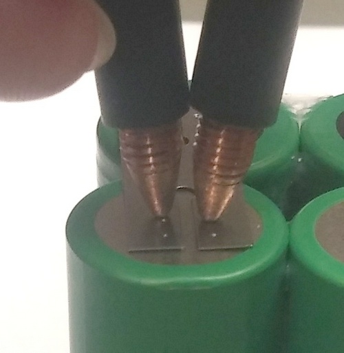
Regarding the spot welder, is that available for purchase? If I were to string only 120 cells, would I need a spot welder or just solder the thing?
I think you are mixing up voltage and wattage. You can get the same wattage from a 1S 12P pack as from a 12S 1P pack. The only problem with low voltage is that you need to handle large currents and use thick wires. The same holds for the motor. Wattage is only related to motor size. You can wind the same motor or 1V or for 100V, it will deliver the same power. By the way, the same holds for transformers or inductors similarly.
The scooter is optimized for usability, and one of the main goals was to make it as light as possible. It weighs only 8kg and this is also because of a tradeoff between battery weight and capacity. With that battery, you can use it roughly for one hour. Peak power is 350W, which is enough to handle moderate slopes. But that is limited by the motor, the current battery can deliver more than 700W. As it is target for daily commuting in public transport, my experience after driving it is that is more than enough. The scooter cannot be used for long trips, but you don’t really want to do this with a kick scooter anyway. Regular electric scooters that you can sit on would be much more suitable.
To your question regarding the motor: the supplier has versions with and without Hall sensor feedback. But neither my concept nor my controller require that. The controller operates sensorless, and the scooter is designed not to start by itself, but to assist you in actively keeping the speed that you give it through kicking.
I don’t understand your question regarding the number of phases. Please show me a brushless motor that has a different number. (Although the question is not stupid, because this motor concept would also work with 2 phases, which would simplify the design of the controller!)
Regarding integrating the BMS into the controller: it was that way in the first design. But I already explained you that this is not allowed per legislation. The battery has to be a self contained and safe solution.
The spot welder is available for purchase, but I am currently out of stock and am waiting for feedback from my customers that I may want to include before launching a second production round. I will accept pre-orders by Sept~Oct and expect to be able to deliver again by Oct~Nov. If you are interested, I suggest to subscribe to the website newsletter.
I just have seen the new progress Frank, OMG……. OMG!!!!!! What a work, and also an amazing design of the protection board for the cells.
Yep German engineering at the top.
WannaDuino